
These common questions are typically associated with configuring BARR/RJE. If you can't find the answer to your question here, click the Index or Search tab of the Help to search for a specific word or phrase.
How do I determine the appropriate connection method when connecting SME to 3745 FEP?
How do I set up an RJE DSPU connection using Microsoft SNA Server?
How do I connect to BARR/RJE through SNA server using an 802.2 link service?
How do I manually create readers for sending jobs to the RJE host?
For an SDLC connection, host personnel must choose whether to use V.35 or RS232 connectivity options. The RS232 option requires a LIC1 card in the FEP, whereas the V.35 option requires a LIC3 card. V.35 is recommended for line speeds of 56K or greater.
You must decide on a clocking The coordination of the computer components' timing. source for the line. There are three clocking sources: the Barr adapter, the FEP, and the modem eliminator. Use the following scenarios to guide you through the clocking source preparations, depending on which connection method you choose. For more information, see the Communication link parameters topic.
Barr adapter
The Barr adapter has the SME cable plugged into an FEP straight-through cable. The Barr adapter has a Winchester male plug and the IBM (FEP) cable end is female. On the FEP, if using a LIC3 card, you will need to use the top port. In your NCP LINE macro, make sure you set CLOCKING=EXT. The software will do the clocking based on the data rate specified on the Link tab. No modem eliminators are necessary.
FEP
Use the bottom port (DCE) on the LIC3 card and connect the IBM SME cable to the Barr adapter's straight-through cable. The NCP will be generated as CLOCKING=INT (or DIRECT). No modem eliminator is needed.
Modem eliminator
The modem eliminator sits between the FEP and the Barr computer. The Barr computer will use the straight-through cable. The FEP will use the top port (DTE) on LIC3 and the straight-through cable. The NCP will be generated for CLOCKING=EXT. The Modem eliminator will have dip switches or another mechanism for setting the clock speed.
To define RJE LUs, enter the LU macro. Use this formula to calculate the number of LUs needed:
|
number of LUs = total printers + total punches + total readers + 2 |
Each LU requires a separate LU macro instruction. The number of RJE sessions that can be simultaneously active equals the number of LUs you define. The number of printers, punches, and readers are specified on the RJE Description tab. You must specify two extra LUs for sending commands from the keyboard and receiving console messages.
 To see how many LUs you are currently using,
from the RJE Configuration Utility's Communication
Link tab, click NCP and Physical Unit. In the definition, view
either the MAXLU
number or the number of LU
names, depending on your link type.
To see how many LUs you are currently using,
from the RJE Configuration Utility's Communication
Link tab, click NCP and Physical Unit. In the definition, view
either the MAXLU
number or the number of LU
names, depending on your link type.
When attempting to connect to the host, you can have the following problems:
The computer stops responding when receiving files
The Barr computer reboots after attempting to write the file
The RJE Diagnostic's Communication scope reads: E41
Various codes appear in the Sense code column
LUs become inactive soon after startup
Some LUs might bind, but the connection is quickly dropped
Sending JCL to the host using BARR/RJE causes the line to disconnect
The host console shows that the program is refusing RUs
The trace shows that Barr sends frames of data, but then receives ACTPU from the host
These problems occur as a result of MAXDATA parameter inconsistencies across the SNA connection. The MAXDATA parameter inconsistencies cause data truncation or parsing delays and problems. The error code E41, if present in a 802.2 connection, indicates that the link was in an invalid state for the command. In this situation, data frames are truncated during file transmission.
Ask the host programmer and network analyst to verify and adjust the MAXDATA parameter in JES, VTAM and the network routers, and the host's BUFSIZE parameter. After these parameters have been set, change MAXDATA in BARR/RJE to the same value using the following steps. For more information, see the Communication link parameters and Remote definition topics.
Open the RJE Configuration Utility.
Under the Connection column, select the connection type and click Modify. The Connection Properties dialog box displays.
On the Communication Link tab, under Connection, click Configure. Depending on your connection, the 802.2 Connection Configuration dialog box or the SDLC Connection Configuration dialog box displays.
Under VTAM parameters (PU macro), select the appropriate value in the MAXDATA drop-down list.
 The maximum MAXDATA value for Ethernet is 1492,
so you must select a value less than that.
The maximum MAXDATA value for Ethernet is 1492,
so you must select a value less than that.
Click OK twice and then click Close.
See also: Configuring VTAM
The BARR/RJE 802.2 link software can connect to a remote host using Microsoft SNA Server as a DSPU.
Complete the following steps to establish a DSPU connection.
Define an upstream link service on the SNA Server that connects to the mainframe. (This is probably already completed.)
Define an 802.2 DLC downstream link service on the SNA Server that points to the MAC address of the BARR/RJE computer. You will also need to define the appropriate number of downstream LUs under the DSPU link service and make them available to the BARR/RJE remote computer. Refer to the Microsoft SNA Server Help for more information.
Configure the 802.2 communication link. The LOCADDR assigned in the BARR/RJE software will be the MAC address of the SNA Server.
After all components are defined and activated, establish the 802.2 connection to the host.
See also: Configuring BARR/RJE for 802.2
You can specify the first character of a host command on the RJE Configuration Utility's Commands tab. When using the RJE Console, the software will automatically add the specified character to the beginning of each command you issue.
Specify a class for the device on the RJE Configuration Utility's Device Properties dialog box or create an override table that will assign a class value.
Either no device or more than one device is providing clocking on the line. The BARR/SYNC adapter looks like a DTE device on your network. The device that the Barr cable plugs into looks like a DCE device. If a Barr RS/232 or V.35 cable is used, the Barr adapter expects internal clocking to be provided by your connecting device. If you would like the Barr adapter to provide external clocking, then you must use a Barr SME cable. For more information, see the Communication link parameters topic.
Multiple 802.2 connections are supported on both the same link service and different link services. In 802.2 connections, the local SAP is related to the link service while the remote SAP is related to the connection. When configuring multiple connections, the link services must have unique local SAPs. Generally, you can use the same link service if you are connecting to different hosts. If you are connecting to the same host, then the DLC layer requires that you allocate a new link service (with a different local SAP) for each connection.
You configure the local SAP from the Link tab when you configure 802.2 for BARR/RJE or BARR/NJE. You configure the remote SAP from the 802.2 Connection Configuration dialog box when you configure 802.2 for BARR/RJE or BARR/NJE.
BARR/RJE with 802.2 LLC2 can be configured to connect as a downstream connection in Microsoft's SNA Server. You must use the following steps in order to configure SNA Server. For more information, see your Microsoft SNA Server Help or the Configuring and testing the SNA gateway topic, depending on the associated program.
Define a DLC 802.2 link service under your Link Services folder in the SNA Server. Take note of the local Service Access Point (SAP) that you use.
Define a standard 802.2 connection under your Connections folder in the SNA Server. You will need to gather information from your host programmer in order to complete all the fields.
Define the LUs that the host has assigned for this connection. Remember that the LU numbers need to match the LOCADDR parameter as defined by the host programmer.
Define a downstream 802.2 connection. The procedure is the same as in step 2, but you select the Downstream option button when defining the connection. Be sure to take note of the remote SAP that you specify.
Assign the LUs that you defined in your upstream connection to the downstream connection. One method is to assign the LUs to a pool. If the LUs are assigned to a pool, then make sure that you assign the pool to your downstream connection multiple times. If only one pooled LU is assigned, the Barr software will only use one LU when it connects.
In the Barr software, on
the RJE Configuration Utility's Communication
Link tab, under Link options,
select the 802.2 LLC2 link service and click Modify.
The BARR/SNA 802.2 Link Service configuration utility Link
tab displays. 
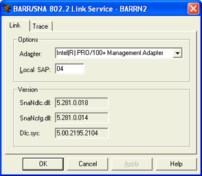
Enter the Local SAP value that you obtained from your Link Services and Connections folders in the SNA Server.
Under Connection,
click Configure. The 802.2
Connection Configuration dialog box displays.
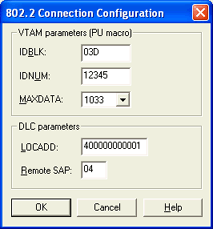
Enter the MAC address of the SNA Server in the LOCADD box. Consult your host programmer for the other values.
Enter the Remote SAP value that you obtained from your Link Services and Connections folders in the SNA Server.
Click OK twice, and then click Close.